ESP32 Wireless Communication - Microcontroller Selection
1. Microcontroller Selection
Based on team subsystem planning:
-
Laksh → PIC (Sensors & HMI)
-
Raunak → PIC (Actuators)
-
Mihir → ESP32 (Wireless Communication)
Microcontrollers Considered
Choice A — ESP32-S3-WROOM-1-N8R8 (selected)
- Link / Datasheet: Datasheet
- Type: Surface-mount module (SMD) with integrated antenna, 8MB flash, 8MB PSRAM
- Pros: Integrated Wi-Fi/BLE, native USB support, 8MB PSRAM enables OV5640 camera frame buffering, large GPIO count, pre-certified RF reduces layout risk, same footprint as N4 variant.
- Cons: Slightly larger footprint and higher per-unit cost than bare chip; module antenna performance depends on board placement.
Choice B — ESP32-WROOM-32 (classic module)
- Link / Datasheet: Datasheet
- Type: Surface-mount module, classic ESP32 (older core)
- Pros: Mature ecosystem, lots of community examples, widely available dev boards for testing.
- Cons: Older architecture (no native USB, less optimized camera/USB support), fewer advanced peripheral features than S3; less headroom for camera streaming.
Choice C — ESP32-S3 (bare QFN chip)
- Link / Datasheet: Datasheet
- Type: Bare QFN package (lowest cost per unit)
- Pros: Smallest PCB footprint, lowest BOM cost (chip only), maximum control over RF layout and BOM.
- Cons: Requires custom RF layout and impedance matching (high risk for first spin), more difficult assembly (QFN), needs certified antenna or careful trace design.
Selection Rationale (summary): The ESP32-S3-WROOM-1-N8R8 (Choice A) gives the best tradeoff of RF reliability, native camera and USB support, 8MB PSRAM for OV5640 frame buffering, and quick bring-up for the wireless gateway role. Choice B lacks PSRAM entirely and cannot support the OV5640 camera at any useful resolution. Choice C is lowest cost but introduces RF design risk unacceptable for a first student PCB.
2. Selected Microcontroller
ESP32-S3-WROOM-1-N8R8
- 41-pin surface-mount module
- Dual-core Xtensa LX7 processor
- Integrated Wi-Fi + BLE
- 8MB flash + 8MB PSRAM
- Native USB support (GPIO19/20)
- Integrated PCB antenna
- 3.3V operating voltage
- Same PCB footprint as N4 variant — drop-in replacement
The module pin layout and definitions are shown in:

Figure 01: ESP32-S3-WROOM-1-N8R8 Module Pin Layout (Top View) (Figure 3.1)
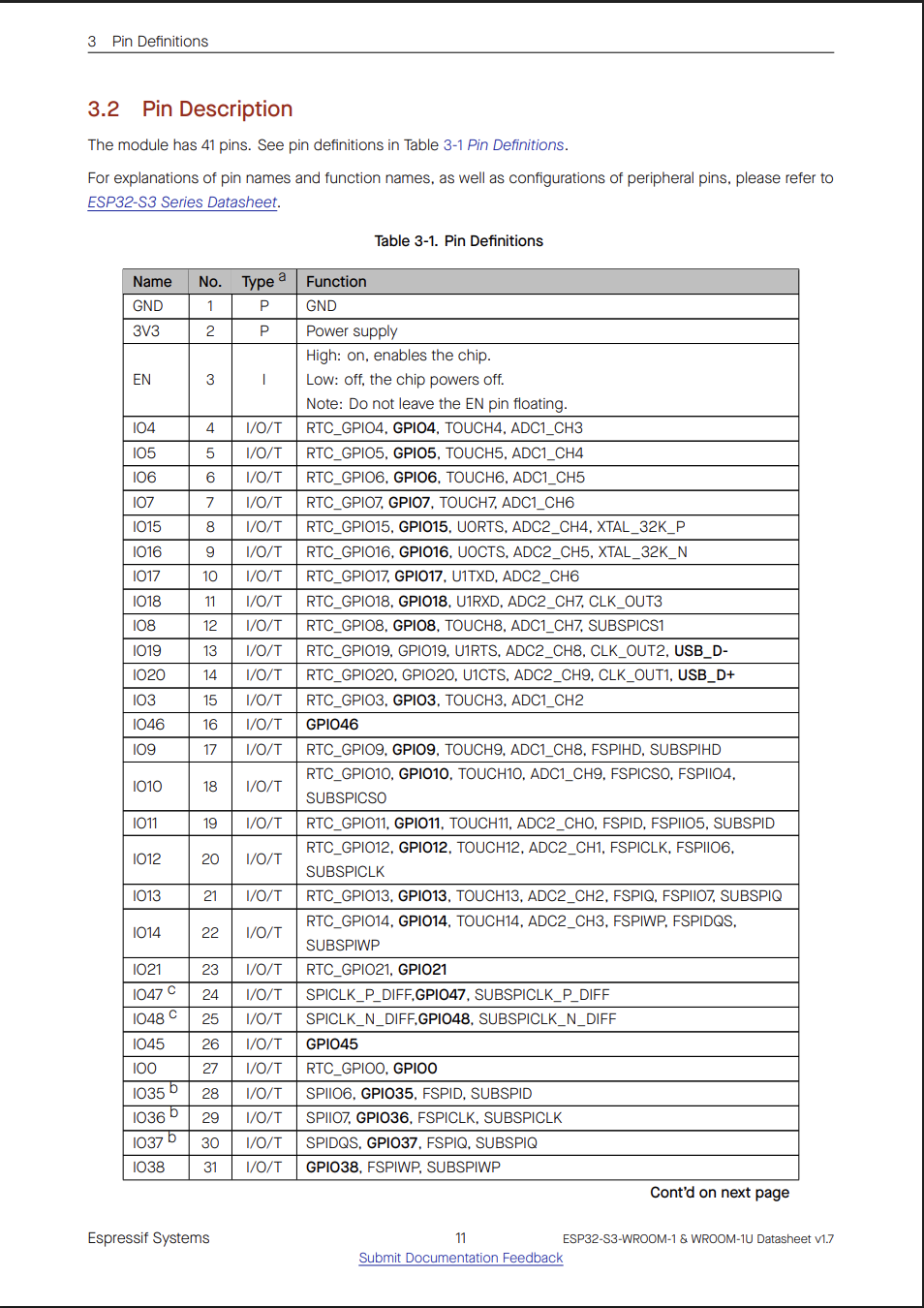
Figure 02: ESP32-S3-WROOM-1-N8R8 - Pin Definitions (Table 3-1, Part 1)
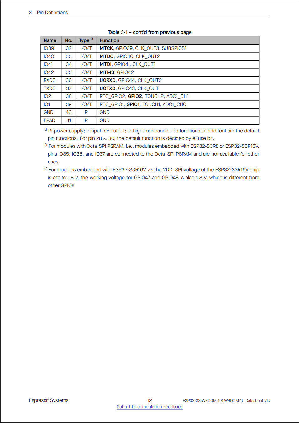
Figure 03: ESP32-S3-WROOM-1-N8R8 - Pin Definitions (Table 3-1, Part 2)
These confirm:
- 3V3 = Pin 2
- GND = Pins 1 and 40
- EPAD = Ground
- RXD0 = Pin 36 (GPIO44)
- TXD0 = Pin 37 (GPIO43)
- USB_D- = GPIO19 (Pin 13)
- USB_D+ = GPIO20 (Pin 14)
3. Project-Specific Requirements
For the wireless subsystem, the required peripherals are:
| Peripheral | Required | Quantity |
|---|---|---|
| UART | Yes | 1 (RX + TX) |
| Wi-Fi | Yes | Integrated |
| Camera Interface | Yes | 1 (OV5640) |
| USB | Yes | 1 |
| GPIO | Yes | 4 Debug LEDs + 1 Power LED |
| PSRAM | Yes | 8MB (OV5640 frame buffers) |
| SPI | No | 0 |
| I2C | No | 0 |
| ADC | No | 0 |
| DAC | No | 0 |
| PWM | Optional | 1 |
Estimated required GPIO count: ~20–22 (includes 8 camera data lines + 6 camera control/sync signals + UART + USB + LEDs)
4. Microcontroller Capability Comparison
| Feature | PIC18F47Q10 | ESP32-S3-WROOM-1-N8R8 | Required? | Result |
|---|---|---|---|---|
| 32-bit CPU | No (8-bit) | Yes | Preferred | ESP32 |
| Wi-Fi | No | Yes | Required | ESP32 |
| UART | Yes | Yes (3) | ≥1 | Both |
| Camera Support (DVP) | No | Yes | Required | ESP32 |
| USB Native | Limited | Yes | Preferred | ESP32 |
| PSRAM | No | Yes (8MB) | Required for OV5640 | ESP32 |
| GPIO Count | ~36 | ~36 | ≥20 | Both |
| Flash | Limited | 8MB | ≥2MB | ESP32 |
Evaluation
The PIC18F47Q10 does not support Wi-Fi, camera streaming, or PSRAM without significant additional hardware. The ESP32-S3-WROOM-1-N8R8 directly satisfies all wireless, streaming, and memory requirements. No critical requirements are unmet by the ESP32.
5. Pin Allocation Table (Verified Against Datasheet and Firmware)
| Function | Module | Pin | GPIO | Notes |
|---|---|---|---|---|
| 3.3V | Power | Pin 2 | 3V3 | |
| GND | Ground | Pins 1, 40 | GND | |
| EPAD | Ground | Center Pad | GND | Exposed pad |
| EN | Pin 3 | EN | Enable | |
| UART TX | Pin 37 | GPIO43 | Daisy-chain TX | |
| UART RX | Pin 36 | GPIO44 | Daisy-chain RX | |
| USB D− | Pin 13 | GPIO19 | Native USB programming (USB_N in schematic) | |
| USB D+ | Pin 14 | GPIO20 | Native USB programming (USB_P in schematic) | |
| MQTT LED | Pin 29 | GPIO36 | MQTT activity indicator | |
| WiFi LED | Pin 28 | GPIO35 | WiFi connected/disconnected indicator | |
| RX LED | Pin 34 | GPIO41 | UART RX indicator | |
| TX LED | Pin 33 | GPIO40 | UART TX indicator | |
| Camera SIOD/SDA | Pin 4 | GPIO4 | OV5640 SCCB data | |
| Camera SIOC/SCL | Pin 22 | GPIO14 | OV5640 SCCB clock | |
| Camera VSYNC | Pin 21 | GPIO13 | Frame sync | |
| Camera HREF | Pin 5 | GPIO5 | Line valid | |
| Camera PCLK | Pin 20 | GPIO12 | Pixel clock | |
| Camera D2 | Pin 9 | GPIO16 | Data bit 2 (LSB) | |
| Camera D3 | Pin 12 | GPIO8 | Data bit 3 | |
| Camera D4 | Pin 8 | GPIO15 | Data bit 4 | |
| Camera D5 | Pin 17 | GPIO9 | Data bit 5 | |
| Camera D6 | Pin 7 | GPIO7 | Data bit 6 | |
| Camera D7 | Pin 18 | GPIO10 | Data bit 7 | |
| Camera D8 | Pin 6 | GPIO6 | Data bit 8 | |
| Camera D9 | Pin 19 | GPIO11 | Data bit 9 (MSB) | |
| Camera RESET | Pin 11 | GPIO18 | OV5640 reset | |
| Camera PWDN | Pin 10 | GPIO17 | OV5640 power down |
Pin Sufficiency Check
Total pins required ≈ 26
Total available GPIO ≈ 36+
There are no pin conflicts. All camera GPIOs (4, 5, 6, 7, 8, 9, 10, 11, 12, 13, 14, 15, 16, 17, 18) are fully clear of UART (GPIO43/44), USB (GPIO19/20), and debug LED (GPIO35–36, GPIO40–41) assignments.
6. Role Description
I am responsible for the Wireless Communication subsystem. My board serves as the gateway between the internal UART daisy-chain system and the external MQTT server over Wi-Fi. I manage publish/subscribe messaging, forward structured UART packets, provide local debug LED indicators for MQTT, WiFi, and UART activity, and designed the subsystem to support live video streaming via the onboard Adafruit OV5640 camera module (5MP, DVP interface). The camera software infrastructure — including frame capture, chunked MQTT publishing, and a laptop-side viewer — was fully implemented, though end-to-end hardware demonstration was not completed within the project timeline. My subsystem isolates wireless complexity from the sensor and actuator subsystems to maintain modularity and simplify debugging.
7. Compatibility & Software Research
Wi-Fi & MQTT
- Fully supported in MicroPython using the
mqtt_asasync library. - Stable networking stack with automatic reconnection handling via
wifi_corocallback. - WiFi connection loss triggers an emergency stop broadcast over UART as a hardware failsafe.
OV5640 Camera
- OV5640 driver requires MicroPython firmware compiled with
esp32-camerasupport enabled. - Requires 8MB PSRAM for frame buffers, satisfied by N8R8 variant.
- Adafruit OV5640 breakout (5841) has onboard oscillator, no XCLK circuit needed on host PCB.
- Camera commands (
capture,stream on,stream off) are handled via both MQTT subscription and UART button events.
UART
- Hardware UART2 used at 9600 baud, TX on GPIO43, RX on GPIO44.
- 64-byte structured packet format with
AZ/YBheader/footer framing. - Rate-limited transmission with 500ms minimum interval between packets.
Known Considerations
- Wi-Fi transmission causes current spikes, handled by AP63203WU-7 2A regulator with adequate headroom.
- OV5640 at VGA resolution uses ~500KB per frame, PSRAM handles this comfortably.
- PSRAM draws ~5mA additional current, negligible impact on power budget.
- Proper decoupling on camera connector 3.3V supply required (10µF + 100nF).
- MicroPython
esp32-cameramodule requires custom firmware build — not available in standard MicroPython releases.
No major compatibility conflicts were identified.
8. Final Microcontroller Selection
Final Choice: ESP32-S3-WROOM-1-N8R8
Data-Driven Rationale
- Only microcontroller variant that directly meets Wi-Fi, camera, and PSRAM requirements simultaneously.
- 8MB PSRAM is essential for OV5640 frame buffering; N4 variant cannot support this camera.
- Integrated antenna reduces RF layout risk on first revision PCB.
- Native USB simplifies firmware flashing without a separate USB-UART bridge chip.
- Satisfies surface-mount requirement with same footprint as N4, no PCB layout changes needed.
- Exceeds GPIO and UART requirements with room to spare.
- Strong MicroPython and ESP-IDF ecosystem support lowers development and debugging risk.
- ~$1.07 cost increase over N4 is justified by the full camera streaming capability gained.
The ESP32-S3-WROOM-1-N8R8 is therefore the optimal and necessary microcontroller for this subsystem.