Module's Block Diagram
Overview
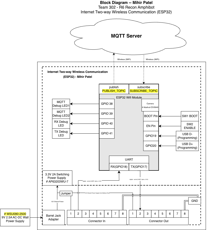
This block diagram represents the ESP32-based Internet Two-way Wireless Communication subsystem developed by Mihir Patel for Team 302 – R6 Recon Amphibot. The purpose of this subsystem is to act as the team's wireless gateway, enabling remote communication with the operator while coordinating data exchange between onboard subsystems through a UART daisy-chain architecture.
The diagram follows the EGR314 block diagram standard and clearly separates this individual subsystem from the rest of the system using a defined subsystem boundary. All major electrical components, communication interfaces, and power paths are shown with labeled signal directions, specific GPIO pin numbers, and voltage levels.
Decision-Making Process and Requirements Alignment
The block diagram was structured around three guiding principles: functional isolation, signal clarity, and EGR314 compliance. The most important early decision was to separate the wireless communication path (Wi-Fi/MQTT) from the wired system communication path (UART daisy-chain) at the block level. This isolation prevents RF interference from coupling into the UART signal lines and makes each communication domain independently verifiable during bring-up.
The subsystem boundary was drawn to include only the components directly owned and operated by this module — the ESP32-S3 module, the OV5640 camera, the AP63203WU-7 regulator, the protection circuitry, and the debug hardware. The two 2×4 IDC ribbon connectors sit at the boundary edge, representing the interface points with the rest of the team's daisy-chain network. This boundary definition directly satisfies the product requirement for modular subsystem isolation: any board in the chain can be disconnected via its jumpers and tested independently without affecting other boards.
The decision to show GPIO numbers explicitly on the diagram (rather than just signal names) was made to support direct schematic cross-referencing. During integration testing, teammates needed to know exactly which physical pins carried UART TX, UART RX, and shared power, so labeling at the GPIO level rather than the peripheral level reduced ambiguity. The power jumper structure was included in the diagram because it represents an active design decision that affects how the board is powered in different test scenarios — showing it in the block diagram communicates that behavior to anyone reading the datasheet without requiring them to trace through the schematic.
The camera block is shown within the subsystem boundary because it communicates exclusively through the ESP32's internal camera interface and does not interact with any shared system bus. Placing it inside the boundary reflects the actual hardware topology and satisfies the product requirement for wireless video transmission without adding complexity to the inter-board protocol.
Subsystem Functionality
The ESP32 Wireless Gateway performs three primary functions within the overall exploration device:
1. Two-Way Wireless Communication
The ESP32 connects to an external MQTT Server over Wi-Fi.
- Telemetry, system status, and debug information are published to
PUBLISH_TOPIC - Incoming control commands are received through
SUBSCRIBE_TOPIC
This satisfies the EGR314 team requirement for bidirectional wireless communication using MQTT.
2. UART Daisy-Chain System Interface
The ESP32 interfaces with neighboring subsystems through a standardized UART daisy-chain:
- RX → GPIO44
- TX → GPIO43
Signals are routed through:
- Upstream Connector In (2×4 IDC, 8-pin)
- Downstream Connector Out (2×4 IDC, 8-pin)
This architecture allows structured messages to pass safely across all boards in the team's daisy-chain network while maintaining modular isolation between subsystems.
3. Local Debug and Status Indication
Multiple GPIO-driven debug LEDs provide real-time visual feedback during operation:
| LED | GPIO | Purpose |
|---|---|---|
| Power LED | 3.3V Rail | Indicates onboard 3.3V power is active |
| MQTT Debug LED 1 | GPIO38 | MQTT publish activity indicator |
| MQTT Debug LED 2 | GPIO39 | MQTT subscribe activity indicator |
| RX Debug LED | GPIO40 | UART receive signal indicator |
| TX Debug LED | GPIO41 | UART transmit signal indicator |
These indicators assist with:
- Hardware bring-up
- Power confirmation
- UART signal verification
- Demonstration clarity during lab testing and the Innovation Showcase
Power Architecture
Power is supplied through an external:
WSU090-2500 9V 2.5A AC-DC wall adapter
The adapter connects via a DC barrel jack, feeding an onboard:
AP63203WU-7 3.3V switching regulator
The regulator provides regulated 3.3V power to:
- ESP32-S3-WROOM-1-N8R8 module
- Adafruit OV5640 camera module
- Debug LEDs
- GPIO headers
- UART daisy-chain connectors
Required EGR314 Power Jumpers
Two jumpers are placed directly before the regulator input to allow selectable power sourcing:
-
9V Supply → Regulator Input
Allows the onboard 9V barrel jack supply to power the regulator. -
Jumper 1 — Shared Bus Power (from IDC connector) → Regulator Input
Allows the shared system power rail from the 2×4 IDC connector to power the regulator.
Only one source should be connected at a time. These jumpers allow the subsystem to:
- Be powered independently from its own 9V adapter
- Be powered from the team's shared bus
- Be safely isolated during debugging and verification
This configuration fully satisfies the EGR314 requirement for jumper-controlled power path selection and subsystem isolation.
Programming and Development Interface
The ESP32-S3 is programmed using its native USB interface:
- USB_N (USB D−) → GPIO19
- USB_P (USB D+) → GPIO20
These net labels (USB_N and USB_P) are used in the schematic and correspond directly to the ESP32-S3's native USB differential pair pins. These signals connect to an onboard Micro USB connector, enabling:
- Direct firmware flashing
- Serial monitoring
- No external USB-to-UART bridge chip required
Two tactile switches support standard ESP32 boot operation:
- SW1 — BOOT Pin: Forces download mode for firmware upload
- SW2 — EN Pin: Manually resets the ESP32
The USB interface is intentionally kept separate from the UART daisy-chain bus to prevent signal interference.
Camera Integration
An Adafruit OV5640 camera module (5MP, DVP interface) is included within the subsystem boundary.
- Communicates internally using the ESP32's native parallel camera interface (DVP)
- Does not share UART, SPI, or I²C system buses
- Streams JPEG frames wirelessly over Wi-Fi via chunked MQTT messages
This enables live reconnaissance capability without interfering with inter-board UART communication. The camera interface uses a dedicated 2×9 pin header (J6) on the PCB, keeping camera signals fully isolated from the daisy-chain connectors.
Design Rationale and Standards Compliance
This block diagram satisfies EGR314 requirements by:
- Clearly identifying the individual subsystem boundary
- Showing all utilized ESP32 peripherals (UART, GPIO, USB, Wi-Fi, Camera)
- Labeling signal directions, GPIO numbers, and voltage levels
- Including both upstream and downstream 2×4 IDC connectors
- Separating wireless networking from wired system communication
- Supporting modular verification and subsystem isolation
By isolating wireless communication and system coordination within the ESP32 gateway, the design improves reliability, scalability, and ease of debugging.
Block Diagram